Deep-dive of ZGC's Architecture
Introduction
In the previous article, we did a high-level overview of ZGC and how to configure it. This article will dive deep into the key implementation details and architectural decisions that guide ZGC.
Concurrency and GC Cycle
One of ZGC's major advantages is its extremely low pause times of under 1 ms. This is accomplished by ZGC being an almost entirely concurrent garbage collector. Below is a chart of some of the high-level processes GCs go through each GC cycle and if the process is performed concurrently(✅):
| Serial | Parallel | G1 | ZGC | |
|---|---|---|---|---|
| Marking | ❌ | ❌ | ✅* | ✅ |
| Relocation/Compaction | ❌ | ❌ | ❌ | ✅ |
| Reference Processing | ❌ | ❌ | ❌** | ✅ |
| Relocation Set Selection | ❌ | ❌ | ❌ | ✅ |
| JNI WeakRef Cleaning | ❌ | ❌ | ❌ | ✅ |
| JNI GlobalRefs Scanning | ❌ | ❌ | ❌ | ✅ |
| Class Unloading | ❌ | ❌ | ❌ | ✅ |
| Thread Stack Scanning | ❌ | ❌ | ❌ | ✅ |
Note: Chart based on JDK 19
* Old Gen only
** Partially concurrent
ZGC being able to handle almost every GC process concurrently essentially turns the pause phases into short synchronization points that don't increase with the live set's size and provide consistent performance regardless of scale.
ZGC GC Cycle
The GC cycle consists of three pauses and three concurrent phases, each with distinct responsibilities. Below is a diagram showing a simplified view of the ZGC's GC cycle:
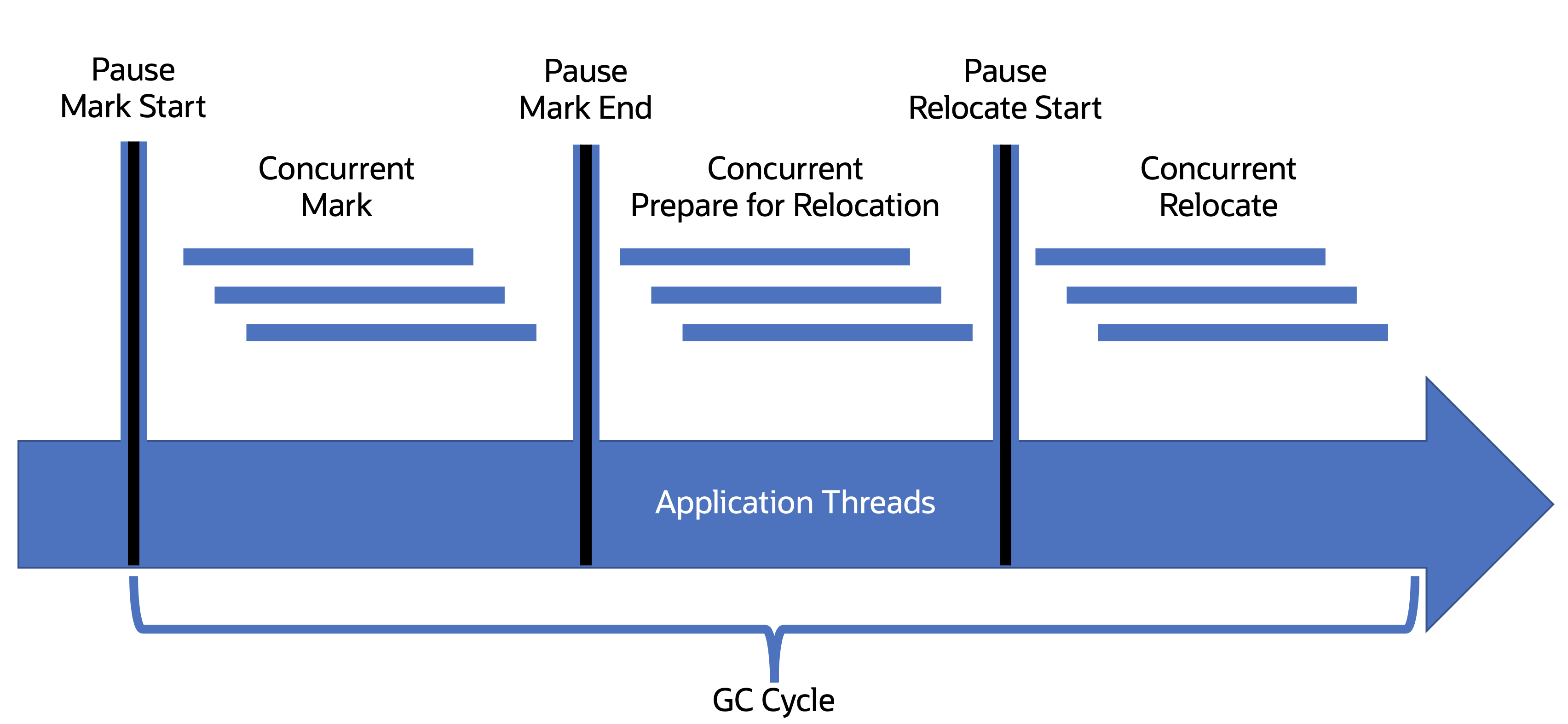
Pause Mark Start
Synchronization point to signal the start of the mark phase.
During this and all pause phases, only minor actions are being taken, like setting boolean flags and what the "good" current global colors are; see Color Pointers.
Concurrent Mark
During this concurrent phase, ZGC will walk the entire object graph and mark all objects.
Pause Mark End
Synchronization point to signal the end of marking.
Concurrent Prepare for Relocation
During this concurrent phase, ZGC will remove objects
Pause Relocate Start
Synchronization point signals to threads that objects will be moved around in the heap.
Concurrent Relocate
During this concurrent phase, ZGC will move objects and compact regions in the heap to free up space. For more on this phase, check the section on compaction.
Colored Pointers
A central part of GC work is to move objects around on the heap while avoiding the application using an outdated reference to a moved object. A straightforward way to achieve that is to pause the application during that work, but for ZGC to achieve its goal of low pause times, it must perform nearly all its work concurrently. You can see the potential issue: Even though ZGC performs its work while the application is running, it must ensure the application always gets the correct reference. It accomplishes this through two key architectural decisions, colored pointers and load barriers. Let’s take a look at colored pointers.
ZGC uses a 64-bit pointer with 20 bits reserved for metadata about the pointer. The 20 metadata bits provide "color" to the pointer that can provide information about the current state of the pointer. Colored pointers are similar to tag and version pointers used in other GC implementations. As of JDK 19, colored pointers in ZGC look like this diagram:
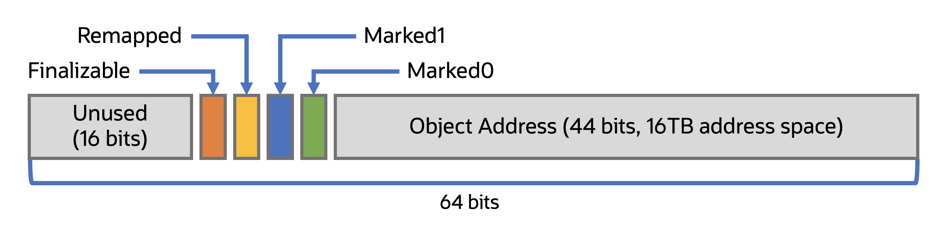
Currently, 4 bits are in use, while the other 16 remain in reserve for future use. The purpose for each bit is as follows:
- Finalizable: This bit indicates if the object is only reachable through a finalizer. Note that finalization was designated as deprecated for removal in JDK 18 with JEP 421: Deprecate Finalization for Removal.
- Remapped: This bit indicates if the pointer is known not to point into the relocation set.
- Marked0 & Marked1: These bits indicate if the object is known to be marked by the GC. ZGC alternates between these two bits as to which is "good" for each GC cycle.
Each bit has a "good" and "bad" color; however, what is a "good" or "bad" color would be context specific to when the object is accessed. The application itself would not be aware of the colored pointers; the reading of colored pointers is handled by load barriers when an object is loaded from heap memory.
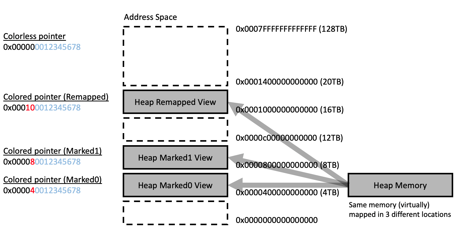
Heap Multi-Mapping
Because ZGC can move the physical location of an object in heap memory while the application is running, multiple paths need to be provided to the current physical location where the object resides. In ZGC, this is accomplished through heap multi-mapping. With multi-mapping, the physical location of an object is mapped to three views in virtual memory, corresponding to each of the pointer's potential "colors". This allows a load barrier to locate an object if it has been moved since the last synchronization point.
A consequence of this design decision is that a system can report ZGC's memory usage as higher than its real usage. This is a consequence of the triplicate addressing of an object in virtual memory; however, the real memory usage is only from where the actual object is located. This can most easily be understood when a system reports memory usage higher than the physical memory installed on the system. The below chart demonstrates what multi-mapping looks like in practice:
Load Barriers
In the previous section, we covered how colored pointers were one of ZGC's major architectural decisions to allow concurrent processing; this section covers the other key architectural decision, load barriers.
Load barriers are code segments injected by the C2 compiler, part of the JIT, into class files when the JVM parses them. Load barriers are added into class files where an object would be retrieved from the heap. The below Java code example shows where a load barrier would be added:
The load barrier adds behavior that will check the "colors" of an object's pointer when loaded from the heap. Load barriers are optimized for the "good" color case, which is the common case, to allow quicker pass-through. Suppose a load barrier encounters a "bad" color. In that case, it will attempt to heal the color, which might mean updating the pointer to put the object's new location on the heap or even relocating the object itself before returning the reference to the system. This healing ensures that subsequent loads of the object from the heap take the fast path.
Regions
ZGC does not treat the heap as a single bucket to toss objects into but dynamically divides the heap into separate memory regions, like in this (simplified) diagram below:
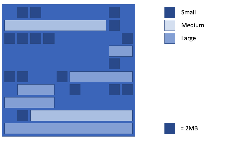
This follows a similar pattern to G1 GC, which also uses memory regions. However, ZGC regions, internally defined as ZPages, are more dynamic, with small, medium, and large sizes; the number of active regions can increase and decrease depending on the needs of the live set.
Dividing the heap into regions can provide several benefits to GC performance, including; the cost of allocating and deallocating a region of a set size would be constant, the GC can deallocate an entire region when all objects within in it are no longer reachable, related objects can be grouped into a region.
Region Sizes
As per the above chart, ZGC has three different sizes for regions; small, medium, and large. It also stands out that, paradoxically, a large region can be smaller than a medium region. The below covers the different region sizes and their purposes.
Small Regions
Small regions are 2 MB in size. Objects less than 1/8th (12.5%) the size of a small region, so less than or equal to 256 KB, are stored in a small region.
Medium Regions
The size of a medium region can vary depending on what the max heap size (-Xmx) is set to. 1 GB or greater and medium regions are set to 32 MB in size; below 128 MB, medium regions are disabled. Like with small regions, objects 1/8th (12.5%) or less in size than the set size of a medium region will be stored there. Below is the chart for the ranges of medium region size:
| Max Heap Size | Medium Region Size |
|---|---|
| >= 1024 MB | 32 MB |
| >= 512 MB | 16 MB |
| >= 256 MB | 8 MB |
| >= 128 MB | 4 MB |
| < 128 MB | off |
Large Regions
Large regions are reserved for humongous objects and are tightly fitted in 2 MB increments to the object's size. So a 13 MB object would be stored in a 14 MB large region. Any object too large to fit in a medium region will be placed in its own large region.
Compaction and Relocation
Regions are designed to take advantage of the fact that most objects created at the same time will leave scope at the same time. However, as implied with the qualifier most, that isn't always the case. Through internal GC heuristics, the GC might eventually copy objects out of a region populated mainly by inaccessible objects into a new region to allow the old region to be deallocated and memory to be freed up. This is called compaction and relocation. ZGC, since JDK 16, accomplishes compaction through two methods of relocation in-place and not-in-place.
Not-in-place relocation is performed when empty regions are available and is ZGC's preferred relocation method. Below is an example of what not-in-place relocation looks like:
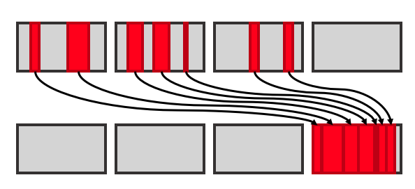
If no empty regions are available, ZGC will use in-place relocation. In this scenario, ZGC will move objects into a sparsely populated region. Below is an example of in-place relocation:
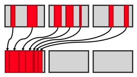
With in-place relocation, ZGC must first compact the objects within the region designated for objects to be relocated into. This can negatively impact performance as only a single thread can perform this work. Increasing heap size can help ZGC avoid having to use in-place relocation.
Additional Reading
Here are a few links that might be worth checking out to learn more about ZGC.
ZGC Team Wiki: https://wiki.openjdk.org/display/zgc/Main
Per Liden's (original developer of ZGC) blog: https://malloc.se/
Deep Dive into ZGC: A Modern Garbage Collector in OpenJDK: https://dl.acm.org/doi/full/10.1145/3538532
More Learning
Last update: March 6, 2022